
BSP vs NPT Threads: Differences and How to Identify Them
Updated · 7 min read
A fitting marked 1/2 inch is not fully identified until you know its thread standard and sealing arrangement. Use this comparison to distinguish BSP from NPT before ordering an adapter or replacement hose assembly.
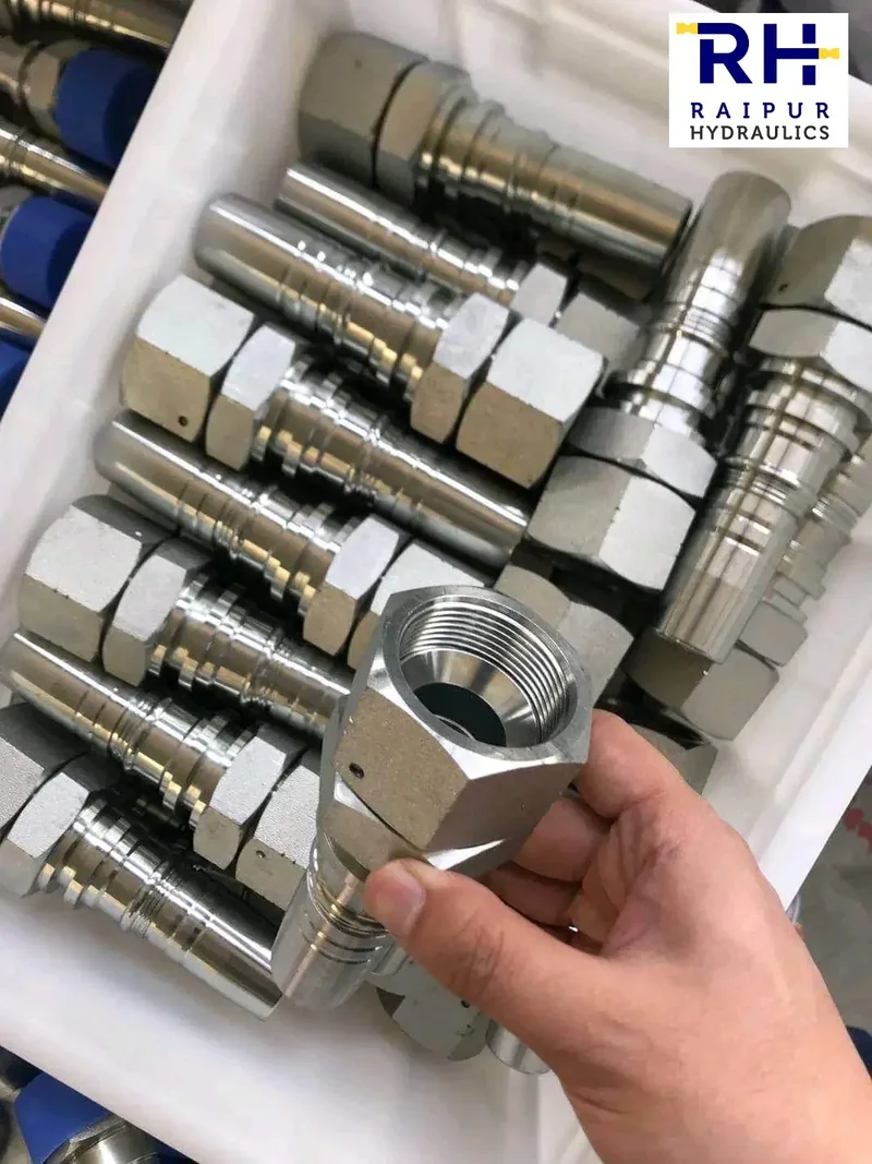
BSP vs NPT: Quick Answer
BSP uses a 55° Whitworth thread form; NPT uses a 60° form. BSP includes parallel G threads under ISO 228-1 and the ISO 7-1 jointing family: taper external R, parallel internal Rp and taper internal Rc; NPT is tapered under ASME B1.20.1. R, Rc and NPT have a 1:16 taper on diameter, meaning the diameter changes by one unit over sixteen axial units. BSP and NPT are not interchangeable, even when the nominal size or TPI matches.
BSPP, BSPT, NPT and NPTF Compared
| Feature | BSPP: G | BSPT Family: R / Rp / Rc | NPT | NPTF Dryseal |
|---|---|---|---|---|
| Standard | ISO 228-1:2000 | ISO 7-1:1994 | ASME B1.20.1-2013 | ASME B1.20.3 |
| Thread Angle | 55° | 55° | 60° | 60° |
| Crest / Root Form | Rounded Whitworth profile | Rounded Whitworth profile | Truncated, usually shown flat; permitted radii within limits | Controlled truncation for crest/root interference |
| Taper on Diameter | None: parallel | R and Rc: 1:16; Rp: parallel | 1:16 | 1:16 |
| Sealing Method | Specified bonded seal, O-ring, face or separate seat | Matching R–Rp or R–Rc threads plus suitable sealant | Matching threads plus suitable sealant | Thread interference; dryseal design per ASME B1.20.3 |
| Common Regional Convention | UK, Europe and many Asian markets | UK, Europe and many Asian markets | North America; also exported equipment | North American dryseal applications; also exported equipment |
Regional conventions are clues, not identification rules. Equipment in India can contain either family, including different connections within one machine. Check the component specification rather than choosing from the machine’s country of origin.
BSPP threads retain the connection mechanically; the designed seal sits elsewhere. Rp is a parallel internal jointing thread, not another name for G. NPTF has additional crest and root control intended to close the leakage path; an unmarked NPT fitting must not be assumed to be dryseal. Follow the fitting manufacturer’s assembly procedure.
BSP vs NPT TPI and Diameter Chart
TPI means threads per inch. Nominal pipe size is a designation, not the measured outside diameter. The BSP column below gives ISO 7-1 basic major diameters at the gauge plane; the corresponding G basic major diameters agree for these nine sizes.
| Nominal Size (Inch) | BSP TPI | BSP Major Ø at Gauge Plane (mm) | NPT TPI | NPT Approx. Major Ø at L1 Plane (mm) |
|---|---|---|---|---|
| 1/8 | 28 | 9.728 | 27 | 10.242 |
| 1/4 | 19 | 13.157 | 18 | 13.616 |
| 3/8 | 19 | 16.662 | 18 | 17.055 |
| 1/2 | 14 | 20.955 | 14 | 21.224 |
| 3/4 | 14 | 26.441 | 14 | 26.569 |
| 1 | 11 | 33.249 | 11.5 | 33.228 |
| 1-1/4 | 11 | 41.910 | 11.5 | 41.985 |
| 1-1/2 | 11 | 47.803 | 11.5 | 48.054 |
| 2 | 11 | 59.614 | 11.5 | 60.092 |
NPT values are calculated at the L1 hand-tight engagement plane from Table 2 pitch diameter E1: approximate major diameter = (E1 + 0.8/TPI) × 25.4 mm. E1 is in inches; 0.8/TPI is the basic thread height. Values are rounded to 0.001 mm and are not nominal pipe OD, tip diameters or acceptance limits.
A caliper reading changes along a tapered thread. Crest truncation, wear, plating and manufacturing tolerances also affect the reading, so compare pitch and form alongside diameter. The extra decimal places describe the calculation, not the accuracy of a field measurement.
Why 1/2 and 3/4 Inch Threads Are Confused
Both families use 14 TPI at 1/2 and 3/4 inch. A pitch blade may therefore appear to fit, and mismatched parts may start together. However, the 55° and 60° flank angles differ, as do the basic diameters: 1/2 BSP is 20.955 mm at its gauge plane, while the calculated NPT reference is about 21.224 mm at L1.
Starting a thread does not prove a compatible joint. Forcing it can damage the flanks or port and leave a leakage path. Extra tightening or sealant cannot correct the underlying geometry. If identity is uncertain, stop assembly and obtain the drawing or appropriate gauges.
How to Identify BSP and NPT in the Field
- Isolate and inspect: depressurise the equipment using its maintenance procedure before disconnecting. Clean the sample and record markings, male or female form, and any damaged threads.
- Measure TPI: fit a thread pitch gauge across several complete threads. Compare the relevant 28/27, 19/18 or 11/11.5 blades; a short contact can hide a mismatch.
- Check the profile: use the correct 55° and 60° pitch/profile gauges. At 14 TPI, pitch alone cannot separate BSP from NPT. Poor access or damaged crests may require specialist gauging or optical comparison.
- Check diameter and taper: measure male OD across crests at separated axial positions, avoiding the chamfer and incomplete threads. A consistent OD suggests parallel form; a changing OD suggests taper. An arbitrary measuring position is not the standard gauge plane.
- Inspect the seal: look for a bonded washer, O-ring, face or cone seat, and compare both mating ends. A parallel female thread could be G or Rp. Confirm the complete connection against its drawing and suitable plug or ring gauges.
Record results together, rather than selecting a standard from one measurement. Use the hydraulic thread identification chart for other families and the BSP thread chart for the wider BSP size range and designation details.
Adapters and Replacement Hose Assemblies
Where the circuit requires different families, select a proper BSP↔NPT adapter with the specified connection at each end. Never force a BSP fitting into an NPT port. Confirm male/female form, nominal size, G/R/Rp/Rc or NPT designation, sealing geometry, material and application suitability before ordering.
An adapter also changes installed length and clearance. Check wrench access and hose routing so the revised connection does not introduce twisting or side load. Thread size by itself does not establish the pressure rating of an adapter or finished assembly.
Browse hydraulic fittings and adapters, or send an RFQ with the part number, clear side and end-face photographs, markings and a drawing if available. Include both end connections and the known service conditions; photographs support identification but do not establish tolerances or a pressure rating.
Data Sources and Basis
BSP TPI and major diameters come from ISO 7-1:1994, Table 1; the G-thread comparison uses ISO 228-1:2000, Table 1. NPT TPI and E1 come from ASME B1.20.1-2013, Table 2, with the diameter calculation based on its basic thread height. These are general engineering references, not RHPL product specifications.
The dimension standards are listed here. Use the applicable standard, product drawing and manufacturer instructions for complete tolerances, gauging and assembly requirements.
- ISO 7-1:1994 — Pipe threads where pressure-tight joints are made on the threads — Part 1: Dimensions, tolerances and designation
- ISO 228-1:2000 — Pipe threads where pressure-tight joints are not made on the threads — Part 1: Dimensions, tolerances and designation
- ASME B1.20.1-2013 — Pipe Threads, General Purpose (Inch)
Frequently Asked Questions
Can BSP and NPT Be Mixed?
No. Their thread forms and dimensions differ. Use a correctly specified BSP-to-NPT adapter when the installation needs both families; do not rely on partial engagement.
Is BSPT the Same as NPT?
No. Both taper forms use 1:16 on diameter, but BSPT has a 55° profile and NPT has a 60° profile. Most listed sizes also have different TPI.
Which Is Used in India?
Both can be encountered. BSP is a common regional convention, while NPT occurs on equipment and components specified for it. Identify each connection from its marking, drawing and measurements.
Do I Need Sealant?
NPT and ISO 7-1 thread-sealing joints need a suitable sealing medium and the specified assembly procedure. G connections seal at their designed face or seat. For NPTF, follow the manufacturer’s dryseal instructions.
Technical References
Consult the current product and equipment instructions for the proposed application. The references below support the general technical background; they do not validate an RHPL assembly.
- ISO 7-1:1994 — Pipe threads where pressure-tight joints are made on the threads — Part 1: Dimensions, tolerances and designation
- ISO 228-1:2000 — Pipe threads where pressure-tight joints are not made on the threads — Part 1: Dimensions, tolerances and designation
- ASME B1.20.1-2013 — Pipe Threads, General Purpose (Inch)
- ASME B1.20.3 — Dryseal Pipe Threads (Inch)
- Swagelok — Thread and End Connection Identification Guide, MS-13-77, revision H
Caterpillar, Volvo, Komatsu, Hitachi, Danfoss, Parker, Manuli and Swagelok are trademarks of their respective owners. RHPL is not affiliated with or endorsed by these brand owners. Gates is a trademark of Gates Corporation; RHPL is an Authorised Gates Distributor. Brand and machine names are used only to identify compatibility. External manufacturer references provide general technical background and do not imply endorsement of RHPL products.