
How to measure hydraulic hose length correctly.
Measure the complete assembly, identify the correct fitting reference points, and give your supplier a dimension that can be manufactured and checked.
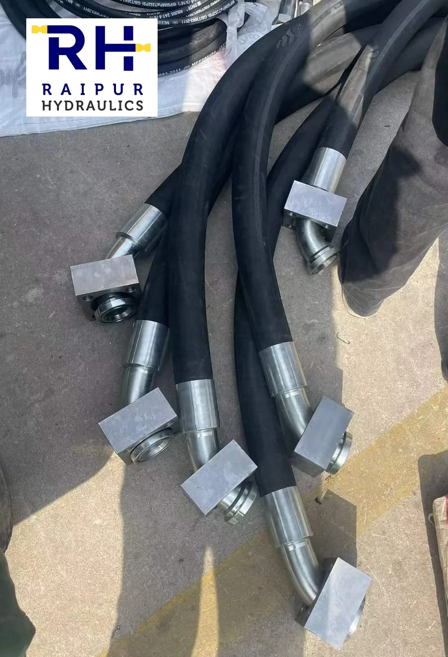
State the length. Show the two datums.
Measure an unloaded, depressurised assembly between the reference points specified for its end fittings. Include the relevant fitting lengths. Do not substitute the visible rubber length or the straight gap across a curved hose.
A datum is the exact point or plane where the dimension starts or ends. Depending on the fitting, it may be a threaded tip, nut end, sealing face or elbow-head centreline. Write the units and mark both datums on the drawing.
The approved OEM drawing and selected hose-and-fitting manufacturer’s instructions establish the actual measurement convention. The diagrams here explain practical examples; they do not create one universal rule for every fitting.
A replacement hose can have the right bore and end connections yet still fit badly if its length is defined incorrectly. A short assembly may load the couplings or restrict movement. Excess length may produce unwanted loops, rubbing or poor bend geometry. The objective is an agreed finished dimension and a route that works throughout the machine’s operating movement.
Assembly length, cut length and exposed hose length
Before using the tape, decide which dimension you need. For customers ordering a replacement, the finished assembly dimension is usually the most useful starting point.
| Dimension | What it means | Use |
|---|---|---|
| Finished assembly length, L | Distance between the agreed fitting datums with the hose positioned as required by the measurement method. | Ordering and inspecting the completed assembly. |
| Hose cut length | Length of the bare hose before fitting insertion and crimping. | Manufacturing, using the selected fittings’ cut-off factors. |
| Exposed hose length | Visible hose between the ferrules or sockets. | Describing visible hose; it does not include hose concealed inside the couplings. |

How to measure a replacement in six steps
- Make the sample safe. Authorised personnel must isolate the equipment, secure moving or supported loads, release stored hydraulic energy and verify zero pressure under the machine’s maintenance procedure. Never loosen a live connection to take a measurement.
- Identify it before removal. Record the machine, circuit or location, original part reference and quantity. Photograph the installed route, clamps and both ends. Label the ends A and B. Record any known routing changes or failure damage.
- Prepare the unloaded assembly. Place the safely removed sample on a clean, level surface. Remove transport caps from the measurement datums when safe to do so. Gently straighten the hose where practicable without stretching, twisting or forcing it beyond its permitted bend geometry.
- Choose both fitting datums. Identify the connection family and end form. Use the supplier’s drawing to decide whether each dimension ends at a tip, nut end, sealing face or elbow centreline. Mark those positions in your sketch.
- Read and repeat. Align a steel tape or suitable rule with the hose axis. Transfer hidden or offset datums with a square; keep the scale in the measurement plane. Read from the actual zero, repeat the measurement and record the unit explicitly, preferably in millimetres.
- Record the complete geometry. Add the End A and End B descriptions, elbow orientation, agreed tolerance and any protection. Check a damaged or altered sample against the approved OEM information or the actual safe routing requirement before ordering.
A worn sample is evidence, not automatically a correct design. A stretched hose, a pulled-out end or a previously incorrect replacement can give the wrong target length.
Where should the tape start and finish?
The fitting name alone is not enough. “Female swivel” can describe different connection families with different measurement references. The following table summarises the conventions illustrated in Parker’s published working-step chart; confirm applicability to your selected parts. Manufacturer datum reference.
| Fitting example | Reference shown in the manufacturer chart | Common error |
|---|---|---|
| Straight male threaded | End of the fitting. | Stopping at the hexagon or ferrule. |
| Straight JIC / SAE / NPSM female, except ORFS | End of the nut. | Assuming every swivel is measured at its sealing head. |
| Straight DIN / BSP / ORFS form | End of the sealing head. | Using a protruding nut edge when it is not the specified datum. |
| Swivel elbow, 45° or 90° | Specified head summit / centreline reference. | Wrapping the tape around the outside of the elbow. |
| Straight flange | Flange face. | Measuring to the clamp, bolt or rear shoulder. |
| Flange elbow | Centreline of the flange face. | Measuring to the outermost elbow metal. |
Straight-to-elbow assemblies
The assembly dimension is referenced to the elbow head’s specified datum in the hose-axis direction. The elbow’s offset is separate geometry. A diagonal tape reading to the lowest nut edge, or a reading around the bend, cannot replace the drawing’s axial dimension.

Flange assemblies
Identify whether each flange end is straight or angled. For a straight flange datum at its connection face, the flange’s rear shoulder is a different plane. For an elbow flange, locate the specified face centreline before transferring the dimension. Removable clamps and bolt heads do not define these datums.

Mixed ends are normal: one assembly may use a male tip at A and an elbow-head reference at B. A written “overall length” without the end descriptions can leave this ambiguous.
Curved hoses: follow the hose path, not the shortcut
If a safely removed hose can be gently laid straight in its unloaded condition, measure it in that position using the agreed fitting datums. If its size, stiffness or set curvature makes that impractical, trace the hose’s centreline with a flexible rule or non-stretch cord and transfer that trace to a straight rule. Include the appropriate end contributions to the agreed datums. Treat this field measurement as approximate until confirmed by the supplier.
Do not measure across the gap between a curved hose’s ends. That is a chord. Do not run the tape along only the inside or outside edge of the bend: the inside route is shorter and the outside route longer than the centreline.

Choosing length for a new installation
First establish the approved route and the two connection positions. Check the complete travel of articulated equipment, steering, booms, cylinders or moving machinery. Allow for the hose’s specified length change under pressure, minimum bend radius and clearance from hot, sharp or moving parts. Keep bends away from the coupling as required by the selected hose manufacturer.
Gates’ routing guidance highlights slack for pressure-related length change, room for flexing, abrasion control and avoidance of twist. Gates routing reference. The resulting length must be checked against the application; a fixed “add 5%” rule cannot account for every route.

Two elbows also need an orientation angle
With bent fittings at both ends, length alone does not fully define an assembly. Two hoses can have the same length and fittings but different relative elbow angles. Twisting the hose to compensate for the wrong angle creates a different installation problem.
Record which end is A, the viewing direction along the hose, the reference position of A, the angular position of B and whether the angle is clockwise or anticlockwise. Use the convention required by the manufacturer or agreed order drawing. Parker’s handbook, for example, defines its own viewing and rotation convention. Orientation reference.

A swivel connection nut generally permits connection tightening. It does not mean a permanently crimped elbow body can be rotated to correct its clocking. Send both a side view for length and an end view for orientation.
Cut length is a manufacturing calculation
For a manufacturer system that uses coupling cut-off factors, the bare hose length is calculated from the finished assembly target:
L = specified finished assembly length. CA and CB = manufacturer cut-off factors for the exact fittings and their stated assembly datums.
The factor is not simply the fitting’s full visible metal length or the ferrule length; part of the hose enters the coupling. Gates publishes this cut-off-factor approach in its hydraulic catalogue. Cut-length reference. Use current values for the exact hose size, fitting part and coupling series.
A 1,500 mm assembly target
If the selected fittings’ confirmed cut-off factors were 45 mm and 55 mm, the calculated hose cut length would be 1,500 − 45 − 55 = 1,400 mm.
These numbers are a teaching example, not an RHPL product specification. They must not be used as default cut-off values. Recheck the completed assembly after manufacture.
Agree the tolerance before manufacture
A target length and a permitted variation are separate requirements. State the nominal length, measurement convention and agreed acceptance tolerance on the order. A universal ±5 mm or ±1% cannot be assumed for every bore, length, hose construction or application.
DIN 20066 addresses assembly dimensions and requirements, while manufacturer handbooks may publish their own applicable tolerance tables. Use the edition required by the order and confirm its actual provisions before accepting or rejecting an assembly. DIN reference. Do not apply an older handbook’s table as an automatically current universal tolerance.
What to send RHPL for a replacement
A clear enquiry connects the measured sample to the required finished assembly. Send the following privately with your request:
- Original part reference, machine and circuit / location, quantity and destination.
- Finished length and units, with A and B measurement datums marked on a sketch.
- End A and End B connection family, thread / flange size, sealing form and straight / 45° / 90° geometry.
- Relative elbow orientation and defined viewing direction, where applicable.
- Hose identification or bore, fluid, working pressure including known peaks, and fluid / ambient temperature.
- Routing movement, protection, clamps, any modifications and the agreed tolerance.
- Clear overview and end photographs; an approved drawing or sample where dimensions cannot be established.
“Finished assembly L = 1,500 mm. Datum A = male fitting tip. Datum B = 90° elbow head centreline per selected fitting drawing. Units: mm. End A and B part details attached. Acceptance tolerance: to be confirmed before manufacture.”
This is a length-note example, not a complete manufacturing specification. A measurement photo should show the zero, both marked datums and the scale. A ruler somewhere in the picture is not enough to establish an accurate dimension.
Need help checking your assembly?
Send RHPL your measured sketch, end photographs and application details for technical review and quotation.
Send your assembly requirement Fitting identification guideFrequently asked questions
Do I include the metal fittings in hydraulic hose length?
For a finished hose assembly, include the fittings up to the agreed measurement datums. The exposed rubber length between ferrules is a different dimension. Identify the fitting form before choosing the datum.
Is every hydraulic hose measured tip to tip?
No. Male threaded tips, swivel-nut ends, sealing heads and elbow centreline datums can differ. Follow the selected manufacturer’s assembly drawing and mark the two measured points.
Should I measure a hose while it is installed?
An installed hose can help document routing, but it may be bent, loaded or inaccessible. For replacement measurement, use a safely removed, depressurised sample where practicable, and confirm its geometry against the equipment requirement.
Can I measure a curved hose across the gap between its ends?
That gives a chord or straight-line end separation, which is generally shorter than the hose path. Gently straighten an unloaded sample if practicable; otherwise trace its centreline and identify the fitting datums.
How much extra hose length should I add?
There is no universal extra percentage. Determine length from the approved route, manufacturer length-change and bend-radius data, movement envelope and fitting geometry. Confirm the final drawing before manufacture.
Does SAE 100R2 or SAE 100R12 specify the assembly length?
These are hose type designations associated with SAE J517. They do not specify the ordered overall length, fitting datums, elbow orientation or acceptance tolerance of your individual assembly.
Can RHPL work from a photograph?
A dimensioned sketch, marked measurement points and clear photographs of both ends help RHPL review the requirement. A photograph alone may not establish exact length, thread pitch, seat type or flange series; an approved sample or drawing may be needed.
SAE, ISO, DIN and manufacturer references
Different documents answer different questions. SAE J1273 and ISO/TS 17165-2 concern assembly practices; ISO 4671 concerns measurement methods; ISO 17165-1 and DIN 20066 concern assembly dimensions and requirements. SAE J517 defines hydraulic hose specifications. None of these references makes an unlabelled length sufficient for every connection.
This article is an original practical explanation using public standard scopes and manufacturer guidance. It does not reproduce normative standard clauses or certify a particular assembly’s compliance. For contractual inspection or manufacture, use the applicable full standard, approved drawing and current part-specific manufacturer instructions.
- SAE J1273_202110 — Recommended Practices for Hydraulic Hose Assemblies
Selection, routing, fabrication, installation and replacement practices.
- SAE J517_202007 — Hydraulic Hose
Hose dimensional and performance specifications; a hose designation does not define the finished assembly length.
- ISO 4671:2022 — Hose dimensions and hose assembly lengths
Measurement methods for hoses and hose assemblies.
- ISO 17165-1:2007 — Dimensions and requirements
Hydraulic hose assembly requirements within the standard’s stated hose and fitting scope.
- ISO/TS 17165-2:2018 — Practices for hydraulic hose assemblies
International guidance on selection, routing, fabrication, installation and maintenance.
- DIN 20066:2021-07 — Hydraulic hose assemblies: dimensions, requirements
German dimensional and requirement standard. Confirm the applicable edition and tolerance requirements in the order.
- Parker WC4400-8/UK — ParLock fitting working steps
Manufacturer diagrams showing different measurement reference points by fitting form (PDF).
- Parker technical handbook — Hydraulic hoses, fittings and equipment
Assembly measurement, relative elbow angle and length tolerances (PDF).
- Gates Safe Hydraulics training posters — Hose routing
Illustrated guidance on slack, flexing, abrasion, minimum bend radius and twist (PDF).
- Gates hydraulic catalogue — Hose cut-length calculation
Manufacturer cut-off-factor method. This is a historical catalogue; use current part-specific dimensions for manufacture (PDF).
Reference review: 2 October 2026. Manufacturer datum examples are system-specific. Diagrams are original RHPL educational schematics, not to scale; photographs are original RHPL website assets.